
A few months ago I was discussing with Juan about his ideas for a charging station for mobile robots. He was already creating several prototypes but I remember suggesting a wireless circuit, an idea that kept bumping inside my mind until a few weeks ago when I found a very cheap (less than €2,5) Qi receiver at bangood:
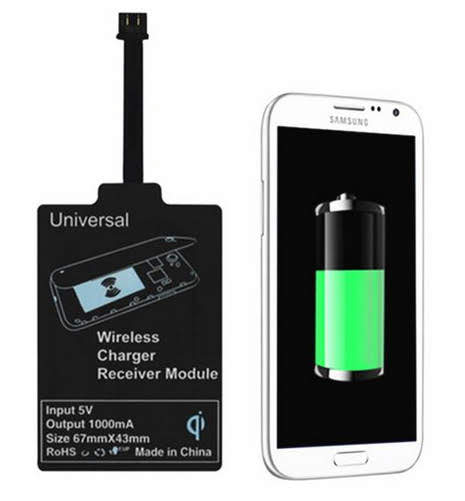
Qi receivers for mobile phones supply only 5V through the USB plug but we can use a boost circuit to raise the voltage. This circuit advertises an output current of 1A, if true (we never know, do we?) doubling the voltage to 10 Volt would reduce the output current to 500 mA with an ideal boost circuit. There are no ideal circuits but at least 400 mA is expected, not great but enough to charge a LEGO robot so lets try…
The remain parts are simple:
- a microUSB breakout board like this one from Adafruit:

Any breakout board is fine as long as it exposes the GND and 5V pins, I got one at a local store for less than €2
- a boost circuit like this one from ITEAD:

There are other models, even cheaper, but I also got this one from a local store and it works good: 2 input pins, 2 output pins and an adjustment potentiometer, that’s it!
– a power plug compatible with LEGO EV3 battery
I cannot suggest a proper plug because I’m not 100% sure of the size… I think it is a 1.7 mm jack like this from Amazon:

I simply cut a plug from a cheap wall charger I had around (not the LEGO one! :D) so I didn’t even had to solder wires
– a couple of wires, preferably red and black
That’s it!
Assembling is very easy so I’m not even goig to draw a circuit:
- solder 2 wires to the microUSB breakout board +5V volt (or VBUS) and GND pins
- solder the other end of those 2 wires to the input pins of the boost circuit (GND to IN- and +5V/VBUS to IN+)
- solder other 2 wires to the output pins of the boost circuit (OUT+ and OUT-)
- solder the other end of thos 2 wires to the jack (OUT- to the outter metal part, OUT+ to the inner part)
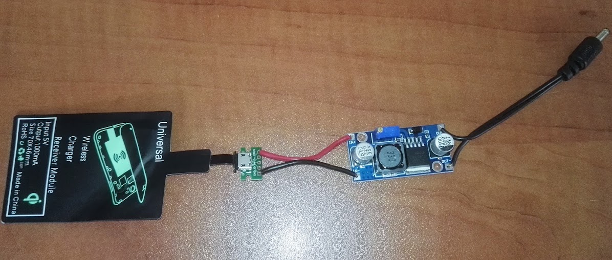
Here a picture with all soldered:
Then you need a voltmeter to adjust the output voltage. Put the Qi receiver over a Qi emitter and assure it’s coupled (most of them give some kind of visual indication of the coupling state like a blue LED) and trim the potentiometer with a small screwdriver until you got 10.0 Volt (you can use higher or lower values but higher will mean less current available so more time to charge and lower might not be enough for the internal circuits of the EV3 battery to work properly).
In this video you can see the green LED of the EV3 battery blinking – that’s part because the Qi receiver wasn’t properly aligned with the Qi emitter, part because both Qi components are low-end quality (the emitter is from a friend, it was a gift at an HP event) and finally part because the Qi emitter was being powered up from my laptop – after switching to a 3.1A wall adapter USB charger I got better performance, even a few millimeters of spacing.