Logic is the beginning of wisdom

This post is part 1 of 8 of  Sniffing the LEGO Interactive Motor

I hope Spock is right because I’m not sure if an headache is a sign of wisdom

First capture

So the only affordable Logic Analyser that works with Linux and I could get nearby to get rid of portuguese evil customs was the BitScope Micro (BS05).

Installation on Ubuntu was easy (amazing how things evolved!) and it works. Documentation isn’t great but it is enough.

Now the tough part: finding sense in all captured data. 300 baud inverted seems… something.

Spock was correct

This post is part 2 of 8 of  Sniffing the LEGO Interactive Motor

And at 57200 57600 bps a pattern at last!!!

So I put Bus Pirate capturing traffic between the LEGO BOOST Hub and the BOOT motor (the one with the encoder that LEGO calls “Interactive Motor“) at 57200.

I ran my serial sniffer:

jpnevulator --ascii --tty /dev/ttyUSB3 --read

I power up the Hub with the motor attached (to port C, not sure if important).

And a pattern of 6 bytes appears:

0A EF EF 00 A0

Where ‘0A’ and ‘A0’ seem “start” and “end” of a message and ‘EF EF 00’ the payload. Or something completely different, like the Monty Python would say.

I connect to the Hub with gatttool in interactive mode and activate notifications and motor readings and then send a command to turn just 1 degree:

char-write-req 0x0f 0100
char-write-req 0x0e 0a004101020100000001
char-write-req 0x0e 0E018101110B0100000064647F03

no events return from the motor but something flows between the Hub and the motor and then the pattern returns:

0A EF EF 00 A0

Thats good! Because I knew that 1 degree is not enough to generate a new position notification (usually 4 to 6 commands are needed) and the payload didn’t change.

1 more command to turn 1 degree. Same

1 more. Same.

1 more. Same. I already sent the same command 4 times.

No 1 more command and a notification is received. And the pattern changes to

0A 00 00 00 A0

There was an increase! But not by +1..

Now I move the axle myself a bit and the payload changes to ’01 00 00′.

I move again backwards so the payload changes back to ’00 00 00′.

Now I send again the same ‘turn 1 degree’ command 5 times… and I get a position change notification and the payload increased to ’01 00 00′ as expected.

So the payload is the encoder position in degrees. 3 bytes, reverted (or little endian).

Edited: spoke too early. 5 bytes message yes, payload related to encoder position yes, payload meaning not so simple.

Not enough yet to use the motor on other systems (like an Arduino or an Ev3) but it is a start. And a drop of wisdom on a hot night after a very pleasant day with family at water sliding park.

just a bit more sense now

This post is part 3 of 8 of  Sniffing the LEGO Interactive Motor

(And I really must be crazy to stay up late doing this)

At 115200 there is also a pattern (and why did I start with 57600?)

00 00 00 00 00 00 00 54 22 00 10 20 B9 
D8 00 00 00 00 00 00 00 00 27
...

First position notification says ’08 00 45 01 00 00 00 00′ so the encoder is at zero.

Sending 5x the command to turn 1 degree I get 3 position changes:

08 00 45 01 01 00 00 00 
08 00 45 01 04 00 00 00 
08 00 45 01 05 00 00 00

(1º, 4º and 5º)

and a decent capture:

D8 00 00 00 00 00 00 00 00 27
D8 00 01 00 00 00 00 00 00 26
D8 00 02 00 00 00 00 00 00 25
D8 00 02 00 00 00 00 00 00 25 
D8 07 03 00 00 00 00 00 00 23
D8 07 04 00 00 00 00 00 00 24
D8 03 05 00 00 00 00 00 00 21
D8 00 05 00 00 00 00 00 00 22

So clearly the 3rd byte is the position (but passing through 2º and 3º seems to have been ignored by the Hub) and the 2nd byte is related to the speed and direction of the rotation.

Now the 1st and last byte: 27 is the ones’ complement of D8

And probably this isn’t the right algorithm but it works at 4 am: if we calculate ‘S’ as the XOR of all payload bytes, the last byte is 27 – S.

Now I ‘just’ need to understand the first bytes received after power up:

00 00 00 00 00 00 00 54 22 00 10 20 B9

It must be the announcement that complements the AutoID…. but does it have some kind of meaning?

Ideas?

The power up sequence of the interactive motor

This post is part 4 of 8 of  Sniffing the LEGO Interactive Motor

This is a typical sequence I get, after powering up the BOOST Hub with the motor already attached to port C:

57 lines of 10 ’00’ bytes

1 line containing the AutoID ’00 00 00 00 54 22 00 10 20 B9′

then the initial status of the encoder is sent (‘D8 00 FF FF FF FF 00 00 00 27’ or ‘D8 00 00 00 00 00 00 00 00 27′) repeating every 0.1 seconds (so each byte takes 10 ms if there is no pause between them).

Not sure about the timings of the AutoID message but the first 63 lines took 1.71126 seconds. This includes 5 encoder status messages so the power up sequence takes only 1.21 seconds and includes 574 ’00’ followed by ’54 22 00 10 20 B9′. If all 580 bytes were timed the same, that would be 2 ms between each.

Need to get back to the logic analyzer to be sure of the timings.

Device 09

This post is part 5 of 8 of  Sniffing the LEGO Interactive Motor

I have a 3V3 FTDI cable with me.

So:

FTDI RX -> BOOST Hub pin 6 (TX)
FTDI TX -> BOOST Hub Pin 5 (RX)
FTDI GND -> BOOST Hub Pin 3 (GND)

Just by connecting it to Port C I get a new device discovered:

0f 00 04 01 01 09 00 00 00 00 00 00 00 00 00

Device Type 09 is a new device. Don’t know what to do with it.

Adding resistors to try to emulate the BOOST Interactive Motor changes nothing.

Tried a few bash scripts to send the power up sequence of the motor… nothing changed. Perhaps bad timings?

Rewired pin 6 to CTS# instead of RX and enabled Handshaking:

stty -F /dev/ttyUSB3 crtscts 115200

Tried again without timings. Nothing changed.

So the only good new is that BOOST detects a UART device as a device of type ’09’ so future hacking will be possible… as soon as we understand it.

Progress at last

This post is part 6 of 8 of  Sniffing the LEGO Interactive Motor

No luck yet with the FTDI cable. But at least I got it with the Bus Pirate!

So:

No LEGO Hub here, just my laptop, the Bus Pirate and the LEGO BOOST Interactive Motor.

Wiring from the Bus Pirate to the Motor:

      • GND -> Pin 3
      • 3V3  -> Pin 4
      • MOSI -> Pin 5
      • MISO -> Pin 6
  • Setup:

Connect the Bus Pirate to the USB port, should show up as ‘/dev/ttyUSB3’.

Access the Bus Pirate with a terminal program like picocom:

picocom -b 115200 /dev/ttyUSB3

Send this commands:

‘m’ to choose mode

‘3’ to choose UART

‘9’ to choose 115200 bps

‘1’ to choose 8 bits without parity (8N)

‘1’ to choose 1 stop bit (so 8N1)

‘1’ to choose receive polarity as Idle = 1 (usual TTL levels)

‘1’ to choose output type ‘Open Drain (H=Hi-Z, L=GND)’

Now that the Bus Pirate is in UART mode:

‘W’ to turn Power Supplies ON (3V3 and 5V pins)

‘P’ to turn Pullup resistors ON

(1) to put the Bus Pirate in ‘Transparent bridge’ mode

‘y’ to confirm

Now quit the terminal (thats Control+A+Q for picocom) and use a serial sniffer like jpnevulator:

jpnevulator -i 10 --tty /dev/ttyUSB3 --read

We should now receive continuous ’00’

Then send the AutoID sequence to the Motor and after that keep sending ’02’ every 100 ms:

#!/usr/bin/env bash

echo -e -n "\x54\x22\x00\x10\x20\xB9" > /dev/ttyUSB3

for i in {1..1000}
do
    echo -e -n "\x02" > /dev/ttyUSB3
    sleep 0.1
done

Sometimes this doesn’t work at first and we just receive a sequence of

C0 00 3F

But aborting the script and trying again will get us:

D8 00 00 00 00 00 00 00 00 27

and if we turn the axle by hand a bit (first clockwise then anticlockwise):

D8 00 01 00 00 00 00 00 00 26
D8 00 02 00 00 00 00 00 00 25
D8 00 03 00 00 00 00 00 00 24
D8 00 04 00 00 00 00 00 00 23
D8 00 03 00 00 00 00 00 00 24
D8 00 02 00 00 00 00 00 00 25
D8 FE 01 00 00 00 00 00 00 D8
D8 00 01 00 00 00 00 00 00 26

If  I stop sending this ’02’ every 100 ms the Motor stops sending the encoder status and returns to ’00’. It also looses it’s current state if I don’t restart the whole script soon enough (or just start ’02’ again).

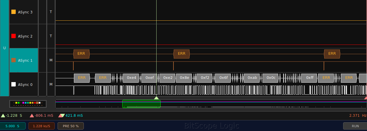
The BitScope logic analyzer wasn’t a great help (except for the timings). I had much more success using the Bus Pirate in ‘Transparent Bridge’ mode to capture each wire of the motor.

Now the reason I cannot replicate this is the FTDI cable is probably the lack of pullup resistors since I’m using a Sparkfun Beefy 3 with an internal PSU that should give enough current to the 3V3 pin. But the Motor also has its own internal pullup and pulldown resistors so this shouldn’t be a problem. is still unknown. Reading the Bus Pirate documentation using the pull up resistors should make no difference because I would also need to manually tie the pull up voltage to 3V3… and I didn’t. Probably the Hi-Z (high impedance) state of the output pin has some importance.

Have to try the FTDI cable again.

Edit: although documentation states that the Bus Pirate pull up resistors also need a manual connection to 3V3… I only have readings when activating the pull ups. And I do have a BP 3.6 board. Go figure.

Edit #2: added “-n” to the test script to prevent sending a New Line (‘0Ah’)

Edit #3: turns out it has nothing to do with pull up resistors or Hi-Z modes… when using picocom to configure the Bus Pirate it changes ‘/dev/ttyUSB3’ to raw mode and leaves it on that mode when quitting… so I can now use jpnevulator to capture all messages from the motor.


FTDI adapter working… sometimes

This post is part 7 of 8 of  Sniffing the LEGO Interactive Motor

Gremlins once again.

BOOST Interactive Motor connected to the FTDI Beefy 3 adapter.

  • Wiring:
    • 6 = RX
    • 5 = TX
    • 4 = 3V3
    • 3 = GND

Just that, no pull up resistors or whatsoever.

When it works, it’s like with the Bus Pirate (including sometimes it just receiving

C0 00 3F

When it doesn’t work… I just get ’00’ after ’00’. Then I remove the 3V3 wire and/or use picocom instead of jpnevulator… and after endless tries it now works?!?

Also changed the FTDI Beefy to another USB port. But if that had any impact it wasn’t immediately.

You ought to love the scientific precision present in these posts 😀

If/when these results gets consistent… I just need an H-Bridge to control the motor and use the FTDI Beefy to read the encoder status. Why didn’t I put an H-Bridge on my holidays luggage?

Edit: found the Gremlin, doesn’t mean I understand it:

Procedure:

1. Connect the FTDI Beefy adapter to USB
2. Start picocom then exit (^A^Q)

 picocom -b 115200 /dev/ttyUSB3

3. Start jpnevulator

jpnevulator -i 10 --tty /dev/ttyUSB3 --read

4. Start adapted shell script and manually remove and reinsert power (3V3) while the Motor is receiving zeros:

#!/usr/bin/env bash

# send lots of 0's
for i in {1..50000}
do
    echo -e -n "\x00" > /dev/ttyUSB3
done

# send Init Sequence
echo -e -n "\x54\x22\x00\x10\x20\xB9" > /dev/ttyUSB3

# send Keep Alive's
for i in {1..50000}
do
    echo -e -n "\x02" > /dev/ttyUSB3
    sleep 0.1
done

So what is this Gremlin inside picocom doing?

From the man page:

Unless the –noinit option is given, it configures the device to the settings specified by the option-arguments (or to some default settings), and sets it to “raw” mode. If –noinit is given, the initialization and configuration is skipped; the device is just opened.

Looks like this “raw” mode is needed for jpnevulator to work. And exiting with ^A^Q  leaves the tty in that mode:

Quit the program *without* reseting the serial port, regardless of the “–noreset” option.

So what is this raw mode and how do I configure it without running picocom? Google points me to Configuring Linux’s serial port to raw mode by Alan C. Assis:

So stty has a ‘raw’ option and this is enough:

stty -F /dev/ttyUSB3 115200 raw

And it works. Yes, it really does!

That’s also the reason Bus Pirate was also working: I was using picocom to configure it.

Argh, so many nights with such a silly issue.

The end is near

This post is part 8 of 8 of  Sniffing the LEGO Interactive Motor

Holidays end today.

And finally got something repeatable with the motor.

The motor talks at 115200 bps, 8N1.

It expects an Init command. And it asks for it (or at least it complains of something). But it also requires some sort of warm up procedure that requires sending to the motor a lot of ’00’ for a while. It seems like a long break before start communication but for some reason it doesn’t work if I use pyserial break command.

Python code here.

Tried to use it in EV3 running ev3dev but no success. 115200 might be to much for the Ev3… or it’s just my bad programming skills.

And this is the FTDI Beefy 3 adapter that I’m using:

To recap the wiring:

  • FTDI GND (black wire) to pin 3
  • FTDI 3V3 (red wire) to pin 4
  • FTDI TX(white/grey wire) to pin 5
  • FTDI RX (green wire) to pin 6

And a sample of the output:

Speed   : 00 (h) =  0 (d)
Position: 00   00   00   00 = 0  degrees
CRC     : 27 (h) =  39 (d)

Speed   : 11 (h) =  17 (d)
Position: 09   00   00   00 = 9  degrees
CRC     : 3F (h) =  63 (d)

Speed   : 1D (h) =  29 (d)
Position: 13   00   00   00 = 19  degrees
CRC     : 29 (h) =  41 (d)

Timeout -> Resync
Speed   : 04 (h) =  4 (d)
Position: 9D   00   00   00 = 157  degrees
CRC     : BE (h) =  190 (d)

Speed   : 00 (h) =  0 (d)
Position: 9D   00   00   00 = 157  degrees
CRC     : BA (h) =  186 (d)

The script is still far from perfect – I was rotating the motor half a turn clockwise and it lost communication in the middle… but at least it reconnected fast enough to preserve position.