FTDI adapter working… sometimes

This post is part 7 of 8 of  Sniffing the LEGO Interactive Motor

Gremlins once again.

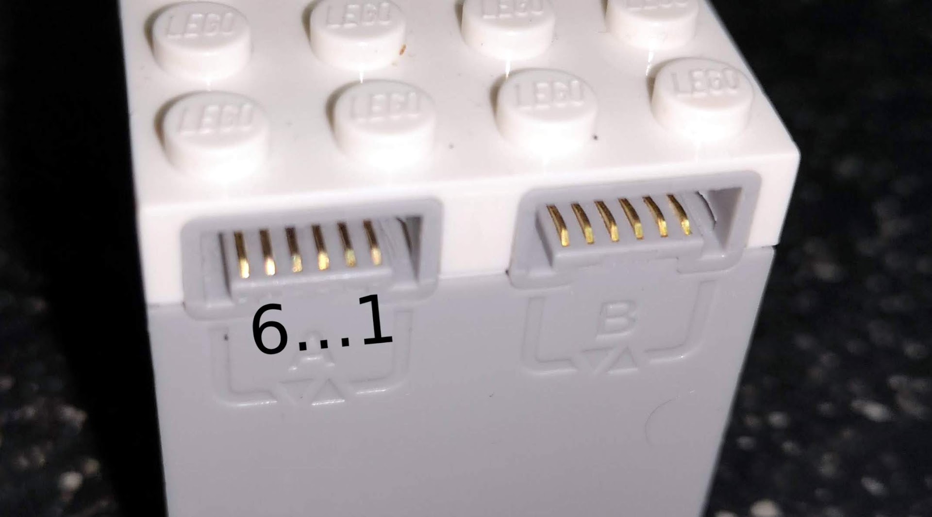
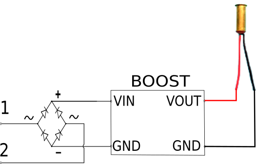
BOOST Interactive Motor connected to the FTDI Beefy 3 adapter.

  • Wiring:
    • 6 = RX
    • 5 = TX
    • 4 = 3V3
    • 3 = GND

Just that, no pull up resistors or whatsoever.

When it works, it’s like with the Bus Pirate (including sometimes it just receiving

C0 00 3F

When it doesn’t work… I just get ’00’ after ’00’. Then I remove the 3V3 wire and/or use picocom instead of jpnevulator… and after endless tries it now works?!?

Also changed the FTDI Beefy to another USB port. But if that had any impact it wasn’t immediately.

You ought to love the scientific precision present in these posts 😀

If/when these results gets consistent… I just need an H-Bridge to control the motor and use the FTDI Beefy to read the encoder status. Why didn’t I put an H-Bridge on my holidays luggage?

Edit: found the Gremlin, doesn’t mean I understand it:

Procedure:

1. Connect the FTDI Beefy adapter to USB
2. Start picocom then exit (^A^Q)

 picocom -b 115200 /dev/ttyUSB3

3. Start jpnevulator

jpnevulator -i 10 --tty /dev/ttyUSB3 --read

4. Start adapted shell script and manually remove and reinsert power (3V3) while the Motor is receiving zeros:

#!/usr/bin/env bash

# send lots of 0's
for i in {1..50000}
do
    echo -e -n "\x00" > /dev/ttyUSB3
done

# send Init Sequence
echo -e -n "\x54\x22\x00\x10\x20\xB9" > /dev/ttyUSB3

# send Keep Alive's
for i in {1..50000}
do
    echo -e -n "\x02" > /dev/ttyUSB3
    sleep 0.1
done

So what is this Gremlin inside picocom doing?

From the man page:

Unless the –noinit option is given, it configures the device to the settings specified by the option-arguments (or to some default settings), and sets it to “raw” mode. If –noinit is given, the initialization and configuration is skipped; the device is just opened.

Looks like this “raw” mode is needed for jpnevulator to work. And exiting with ^A^Q  leaves the tty in that mode:

Quit the program *without* reseting the serial port, regardless of the “–noreset” option.

So what is this raw mode and how do I configure it without running picocom? Google points me to Configuring Linux’s serial port to raw mode by Alan C. Assis:

So stty has a ‘raw’ option and this is enough:

stty -F /dev/ttyUSB3 115200 raw

And it works. Yes, it really does!

That’s also the reason Bus Pirate was also working: I was using picocom to configure it.

Argh, so many nights with such a silly issue.

Progress at last

This post is part 6 of 8 of  Sniffing the LEGO Interactive Motor

No luck yet with the FTDI cable. But at least I got it with the Bus Pirate!

So:

No LEGO Hub here, just my laptop, the Bus Pirate and the LEGO BOOST Interactive Motor.

Wiring from the Bus Pirate to the Motor:

      • GND -> Pin 3
      • 3V3  -> Pin 4
      • MOSI -> Pin 5
      • MISO -> Pin 6
  • Setup:

Connect the Bus Pirate to the USB port, should show up as ‘/dev/ttyUSB3’.

Access the Bus Pirate with a terminal program like picocom:

picocom -b 115200 /dev/ttyUSB3

Send this commands:

‘m’ to choose mode

‘3’ to choose UART

‘9’ to choose 115200 bps

‘1’ to choose 8 bits without parity (8N)

‘1’ to choose 1 stop bit (so 8N1)

‘1’ to choose receive polarity as Idle = 1 (usual TTL levels)

‘1’ to choose output type ‘Open Drain (H=Hi-Z, L=GND)’

Now that the Bus Pirate is in UART mode:

‘W’ to turn Power Supplies ON (3V3 and 5V pins)

‘P’ to turn Pullup resistors ON

(1) to put the Bus Pirate in ‘Transparent bridge’ mode

‘y’ to confirm

Now quit the terminal (thats Control+A+Q for picocom) and use a serial sniffer like jpnevulator:

jpnevulator -i 10 --tty /dev/ttyUSB3 --read

We should now receive continuous ’00’

Then send the AutoID sequence to the Motor and after that keep sending ’02’ every 100 ms:

#!/usr/bin/env bash

echo -e -n "\x54\x22\x00\x10\x20\xB9" > /dev/ttyUSB3

for i in {1..1000}
do
    echo -e -n "\x02" > /dev/ttyUSB3
    sleep 0.1
done

Sometimes this doesn’t work at first and we just receive a sequence of

C0 00 3F

But aborting the script and trying again will get us:

D8 00 00 00 00 00 00 00 00 27

and if we turn the axle by hand a bit (first clockwise then anticlockwise):

D8 00 01 00 00 00 00 00 00 26
D8 00 02 00 00 00 00 00 00 25
D8 00 03 00 00 00 00 00 00 24
D8 00 04 00 00 00 00 00 00 23
D8 00 03 00 00 00 00 00 00 24
D8 00 02 00 00 00 00 00 00 25
D8 FE 01 00 00 00 00 00 00 D8
D8 00 01 00 00 00 00 00 00 26

If  I stop sending this ’02’ every 100 ms the Motor stops sending the encoder status and returns to ’00’. It also looses it’s current state if I don’t restart the whole script soon enough (or just start ’02’ again).

The BitScope logic analyzer wasn’t a great help (except for the timings). I had much more success using the Bus Pirate in ‘Transparent Bridge’ mode to capture each wire of the motor.

Now the reason I cannot replicate this is the FTDI cable is probably the lack of pullup resistors since I’m using a Sparkfun Beefy 3 with an internal PSU that should give enough current to the 3V3 pin. But the Motor also has its own internal pullup and pulldown resistors so this shouldn’t be a problem. is still unknown. Reading the Bus Pirate documentation using the pull up resistors should make no difference because I would also need to manually tie the pull up voltage to 3V3… and I didn’t. Probably the Hi-Z (high impedance) state of the output pin has some importance.

Have to try the FTDI cable again.

Edit: although documentation states that the Bus Pirate pull up resistors also need a manual connection to 3V3… I only have readings when activating the pull ups. And I do have a BP 3.6 board. Go figure.

Edit #2: added “-n” to the test script to prevent sending a New Line (‘0Ah’)

Edit #3: turns out it has nothing to do with pull up resistors or Hi-Z modes… when using picocom to configure the Bus Pirate it changes ‘/dev/ttyUSB3’ to raw mode and leaves it on that mode when quitting… so I can now use jpnevulator to capture all messages from the motor.


Device 09

This post is part 5 of 8 of  Sniffing the LEGO Interactive Motor

I have a 3V3 FTDI cable with me.

So:

FTDI RX -> BOOST Hub pin 6 (TX)
FTDI TX -> BOOST Hub Pin 5 (RX)
FTDI GND -> BOOST Hub Pin 3 (GND)

Just by connecting it to Port C I get a new device discovered:

0f 00 04 01 01 09 00 00 00 00 00 00 00 00 00

Device Type 09 is a new device. Don’t know what to do with it.

Adding resistors to try to emulate the BOOST Interactive Motor changes nothing.

Tried a few bash scripts to send the power up sequence of the motor… nothing changed. Perhaps bad timings?

Rewired pin 6 to CTS# instead of RX and enabled Handshaking:

stty -F /dev/ttyUSB3 crtscts 115200

Tried again without timings. Nothing changed.

So the only good new is that BOOST detects a UART device as a device of type ’09’ so future hacking will be possible… as soon as we understand it.

The power up sequence of the interactive motor

This post is part 4 of 8 of  Sniffing the LEGO Interactive Motor

This is a typical sequence I get, after powering up the BOOST Hub with the motor already attached to port C:

57 lines of 10 ’00’ bytes

1 line containing the AutoID ’00 00 00 00 54 22 00 10 20 B9′

then the initial status of the encoder is sent (‘D8 00 FF FF FF FF 00 00 00 27’ or ‘D8 00 00 00 00 00 00 00 00 27′) repeating every 0.1 seconds (so each byte takes 10 ms if there is no pause between them).

Not sure about the timings of the AutoID message but the first 63 lines took 1.71126 seconds. This includes 5 encoder status messages so the power up sequence takes only 1.21 seconds and includes 574 ’00’ followed by ’54 22 00 10 20 B9′. If all 580 bytes were timed the same, that would be 2 ms between each.

Need to get back to the logic analyzer to be sure of the timings.

just a bit more sense now

This post is part 3 of 8 of  Sniffing the LEGO Interactive Motor

(And I really must be crazy to stay up late doing this)

At 115200 there is also a pattern (and why did I start with 57600?)

00 00 00 00 00 00 00 54 22 00 10 20 B9 
D8 00 00 00 00 00 00 00 00 27
...

First position notification says ’08 00 45 01 00 00 00 00′ so the encoder is at zero.

Sending 5x the command to turn 1 degree I get 3 position changes:

08 00 45 01 01 00 00 00 
08 00 45 01 04 00 00 00 
08 00 45 01 05 00 00 00

(1º, 4º and 5º)

and a decent capture:

D8 00 00 00 00 00 00 00 00 27
D8 00 01 00 00 00 00 00 00 26
D8 00 02 00 00 00 00 00 00 25
D8 00 02 00 00 00 00 00 00 25 
D8 07 03 00 00 00 00 00 00 23
D8 07 04 00 00 00 00 00 00 24
D8 03 05 00 00 00 00 00 00 21
D8 00 05 00 00 00 00 00 00 22

So clearly the 3rd byte is the position (but passing through 2º and 3º seems to have been ignored by the Hub) and the 2nd byte is related to the speed and direction of the rotation.

Now the 1st and last byte: 27 is the ones’ complement of D8

And probably this isn’t the right algorithm but it works at 4 am: if we calculate ‘S’ as the XOR of all payload bytes, the last byte is 27 – S.

Now I ‘just’ need to understand the first bytes received after power up:

00 00 00 00 00 00 00 54 22 00 10 20 B9

It must be the announcement that complements the AutoID…. but does it have some kind of meaning?

Ideas?

Spock was correct

This post is part 2 of 8 of  Sniffing the LEGO Interactive Motor

And at 57200 57600 bps a pattern at last!!!

So I put Bus Pirate capturing traffic between the LEGO BOOST Hub and the BOOT motor (the one with the encoder that LEGO calls “Interactive Motor“) at 57200.

I ran my serial sniffer:

jpnevulator --ascii --tty /dev/ttyUSB3 --read

I power up the Hub with the motor attached (to port C, not sure if important).

And a pattern of 6 bytes appears:

0A EF EF 00 A0

Where ‘0A’ and ‘A0’ seem “start” and “end” of a message and ‘EF EF 00’ the payload. Or something completely different, like the Monty Python would say.

I connect to the Hub with gatttool in interactive mode and activate notifications and motor readings and then send a command to turn just 1 degree:

char-write-req 0x0f 0100
char-write-req 0x0e 0a004101020100000001
char-write-req 0x0e 0E018101110B0100000064647F03

no events return from the motor but something flows between the Hub and the motor and then the pattern returns:

0A EF EF 00 A0

Thats good! Because I knew that 1 degree is not enough to generate a new position notification (usually 4 to 6 commands are needed) and the payload didn’t change.

1 more command to turn 1 degree. Same

1 more. Same.

1 more. Same. I already sent the same command 4 times.

No 1 more command and a notification is received. And the pattern changes to

0A 00 00 00 A0

There was an increase! But not by +1..

Now I move the axle myself a bit and the payload changes to ’01 00 00′.

I move again backwards so the payload changes back to ’00 00 00′.

Now I send again the same ‘turn 1 degree’ command 5 times… and I get a position change notification and the payload increased to ’01 00 00′ as expected.

So the payload is the encoder position in degrees. 3 bytes, reverted (or little endian).

Edited: spoke too early. 5 bytes message yes, payload related to encoder position yes, payload meaning not so simple.

Not enough yet to use the motor on other systems (like an Arduino or an Ev3) but it is a start. And a drop of wisdom on a hot night after a very pleasant day with family at water sliding park.

Powered Up AutoID’s

Notes to myself:

AutoID’s:

  • Train Motor:
    • pin 5 shorted to 4 (VCC)
    • pin 6 shorted to 3 (GND)
  • M Motor:
    • 2k2 between pin 3 (GND) and pin 5
    • pin 6 shorted to 3 (GND)
  • Lights (needs confirmation):
    • 2k2 between pin 3 (GND) and pin 5
  • Tacho Motor (needs confirmation):
    • 2k2 between pin 3 (GND) and 4 (VCC)
    • 2M2 between pin 3 (GND) and 5
    • 2M2 between pin 3 (GND) and 6
    • 2M2 between pin 4 (VCC) and 5
    • 2M2 between pin 4 (VCC) and 6
  • WeDo 2.0 Motion Sensor:
    • 2k2 between pin 3 (GND) and 4 (VCC)
    • 135k between pin 3 (GND) and 5
    • 135k between pin 3 (GND) and 6
    • 135k between pin 4 (VCC) and 5
    • 135k between pin 4 (VCC) and 6
  • WeDo 2.0 Tilt Sensor:
    • 2k2 between pin 3 (GND) and 4 (VCC)
    • 135k between pin 3 (GND) and 5
    • 135k between pin 3 (GND) and 6
    • 135k between pin 4 (VCC) and 5
    • 135k between pin 4 (VCC) and 5

On the Tacho Motor the 2.2 MΩ measured between both GND and VCC and pin 5 and pin 6 make me think on a voltage divider but values are high. Also the 2.2 kΩ between GND and VCC puzzles me (other devices don’t have it).

The WeDo 2.0 Motion Sensor also has 2k2 between GND and VCC. Hmm… the same with the WeDo 2.0 Tilt sensor. But not the BOOST Color&Distance Sensor (11k).

The two WeDo 2.0 sensors (Motion and Tilt) have same measured resistance. So the AutoID ought to be completed by the protocol.

Also:

VCC is 3.3V

The Powered Up Smoke Engine

This post is part 2 of 2 of  Gatto Negro

I will now explain how to connect a smoke engine to the Powered Up Hub – a method that can be used for several type of electric or electronic devices, not just a smoke generator.

First we need to remember the pinout. I show here the female plug on the hub, it’s easier to see the pins:

Powered Up female connector

Thanks to JopieK who opened up is PUP Train Motor for the good of science we already know the names given to each pin by LEGO:

1 – M1
2 – M2
3 – GND
4 – VCC
5 – ID1
6 – ID2

These are the names from the Train Motor side, not necessarily from the Hub side (some of us suspect that pin 5 and pin 6 combine Analog Input and UART functions). For this post purpose these names are enough.

So to emulate a PUP Train Motor we just need to short ID1 to VCC and ID2 to GND and use the M1 and M2 pins:

Powered Up cable hack – train

So I used a PF2 available cable (don’t ask) and stripped the insulation off, joined wire 3 to wire 6 and wire 4 to wire 5 and soldered these two junctions:

Powered Up cable with Train Motor AutoID

Then used heat shrinking tube to isolate these junctions:

The two remaining wires can now be used to control anything we want with a PWM signal of  near 9 Volt (from M1 to M2 or M2 to M1, depending on the direction we choose for the “train motor”). This is the same signal of Power Functions so if we want to connect a LEGO PF motor we just need to connect these two wires to C1 and C2 of a PF connector.

But I want to use a Seuthe Nr. 99 smoke generator for H0 scale trains:

This little device operates with a voltage between 8 and 14 Volt and consuming around 140 mA. My previous experiments with PF revealed that I would need more than just 8V so direct attaching it to a PF cable wasn’t enough, I needed a boost circuit to raise voltage a bit – I used a small circuit and trimmed it to ~11.2 V.

It worked quite well with my PF version of the BR80 so I just reused the circuit, replacing the PF cable with this PUP cable:

Final cable

The circuit is very simple, just a small rectifier bridge and a pre-assembled small boost circuit (Pololu Adjustable Boost Regulator 4-25V, item #799):

The rectifier bridge’s function is to prevent damage to the boost circuit that don’t work with negative voltages when we reverse the direction of the “motor train”.

So how does it work?

Since we are using the same AutoID of the PUP Train Motor, the Hub will notice it as such when we connect this PUP Smoke Engine. So if we use a PUP Handset we just need to press + or – button a few times until the “train motor” receives enough voltage for the boost circuit to work and heats the Seuthe to produce smoke. Same if we use the LEGO App… unfortunately with my BR80 the App doesn’t work because the PUP M motor is not accepted as a valid train motor.

So I made my own ‘Gatto Negro’ App.


Smoke generator for LEGO Powered Up Train

This post is part 1 of 2 of  Gatto Negro

A few months ago I have made my own version of Holger Matthes’ BR80. It was not a full replica because I didn’t have all the pieces required so I had to improvise. I also opted for an all-black version instead of a black+red combination.

I decided I needed a steam engine after some experiments with a MINDSTORMS EV3 setup with a train turntable, two rail switches and a pseudo train with SBrick and RFID:

After I added a mechanism to disengage the train engine from the cargo wagon I decided I needed a steam engine since modern trains don’t need the turntable to operate.

As the SBrick had 4 outputs and I was only using 2 for the motor and the lights I wonder what else could I add to it. Choosed two extra functions that would look good on a LUG exhibition:

  • a smoke engine
  • a horn

The initial project was dismantled but I’m now returning to it with a MILS-based layout to use in larger dioramas with other PLUG fellows:

Currently the turntable and the rail switches are still manually operated but at least I now have a steam engine. With real smoke:

This is ‘Gatto Negro’. It means ‘Black Catt’, I’m using the extra ‘T’ because in Bluetooth Low Energy jargon ‘GATT’ means ‘General Attributes’ and I’ve been using a lot the linux command ‘gatttool’ to quickly test my BLE devices.

Of course ‘Gatto Negro’ is also BLE – it uses the new LEGO Powered Up hub and the PUP version of the LEGO Medium motor instead of the Power Functions IR Receiver, LiPo battery and M motor.

Unfortunately with the current firmware of the PUP Hub using a M motor isn’t the best option: the remote BLE Handset doesn’t hold the speed setting so we have to control the train with short or long button presses, always at full speed. Same happens with current LEGO App because LEGO programmers decided that only a train motor should be used for trains (each PUP device has an unique AutoID and the App was made to use train motors with train controls and non-train motors with car controls).

So I made my own ‘Gatto Negro’ aplication, with MIT AI2.

Next posts I’ll write about the smoke generator and the App.