I got one!
Yes, I bought a Microsoft device. A Xbox Adaptive Controller.
Yes, it is from Microsoft and no I don’t have a Xbox nor even a Windows PC. But it is also a USB HID device.
When it was announced, I liked the simplicity of the idea: a USB controller with lots of digital inputs and also some analog inputs with pretty common connectors: 3.5 mm audio jacks! (yes, TLG, common connectors!!!). And although not officially announced as so, it was not a closed device – it was meant to extend the gaming experience and not only for Microsoft systems.
And it also reminded me the LEGO DACTA Interface A but with inputs only, no outputs.
So now that it is available I ordered one. It arrived today… and linux thinks it is some kind of joystick.
dmsg:
usb 1-6.2: new full-speed USB device number 9 using xhci_hcd
usb 1-6.2: New USB device found, idVendor=045e, idProduct=0b0a
usb 1-6.2: New USB device strings: Mfr=1, Product=2, SerialNumber=3
usb 1-6.2: Product: Controller
usb 1-6.2: Manufacturer: Microsoft
usb 1-6.2: SerialNumber: 3032353630303131363937383235
input: Generic X-Box pad as /devices/pci0000:00/0000:00:14.0/usb1/1-6/1-6.2/1-6.2:1.0/input/input23
usbcore: registered new interface driver xpad
ls -l /dev/input/by-id/ :
lrwxrwxrwx 1 root root 10 out 1 14:56 usb-Microsoft_Controller_3032353630303131363937383235-event-joystick -> ../event22
lrwxrwxrwx 1 root root 6 out 1 14:56 usb-Microsoft_Controller_3032353630303131363937383235-joystick -> ../js0
Since I got a joystick (‘/dev/input/js0’) let’s test it with jstest:
jstest /dev/input/js0

Axes: 0: 0 1: 0 2:-32767 3: 0 4: 0 5:-32767 6: 0 7: 0 Buttons: 0:off 1:off 2:off 3:off 4:off 5:off 6:off 7:off 8:off 9:off 10:off
The black cross-shaped pad is mapped to Axle 6 (Left: -32767 / Right: 32767) and Axle 7 (Up: -32767 / Down: 32767).
The ‘View’ button is Button 6, the ‘Menu’ button is Button 7 and the big black round buttons (‘A’ and ‘B’) are Button 0 and Button 1. No action detected when pressing the ‘Xbox’ and the ‘Profile’ buttons.
Now if I connect a 3.5 mm jack to the first plug (with the symbol of an arrow to the left and a cross) and shunt it I get ‘-32767’ at Axle 6… the same as pressing the left part of the black cross pad. In fact, the 4 first jacks are mapped to Axle 6 and 7 (left, up, down and right).
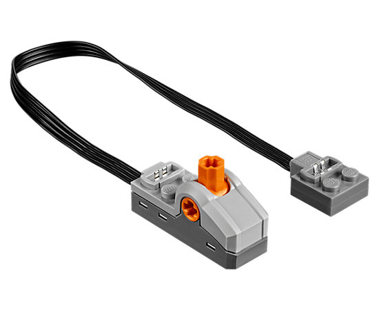
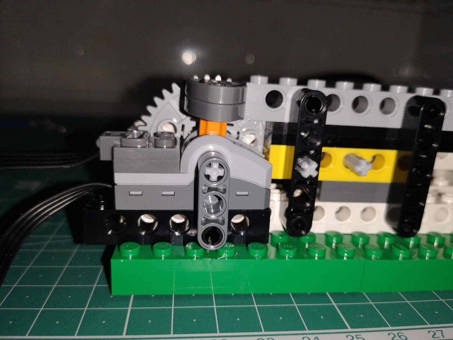
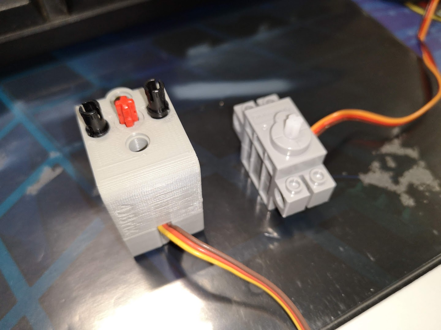
So I can connect any kind of switch to these jacks. Including, of course, LEGO switches 🙂
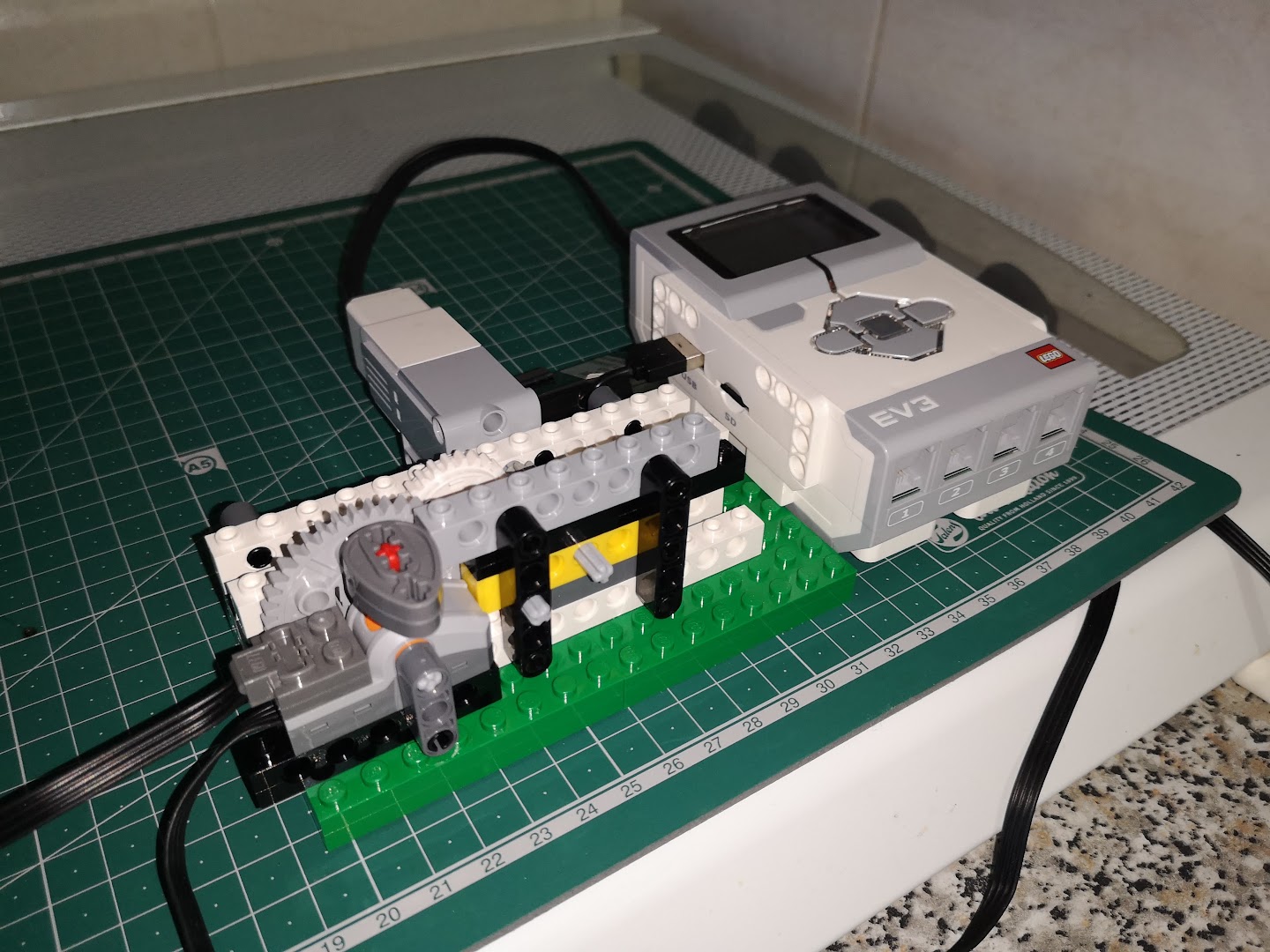
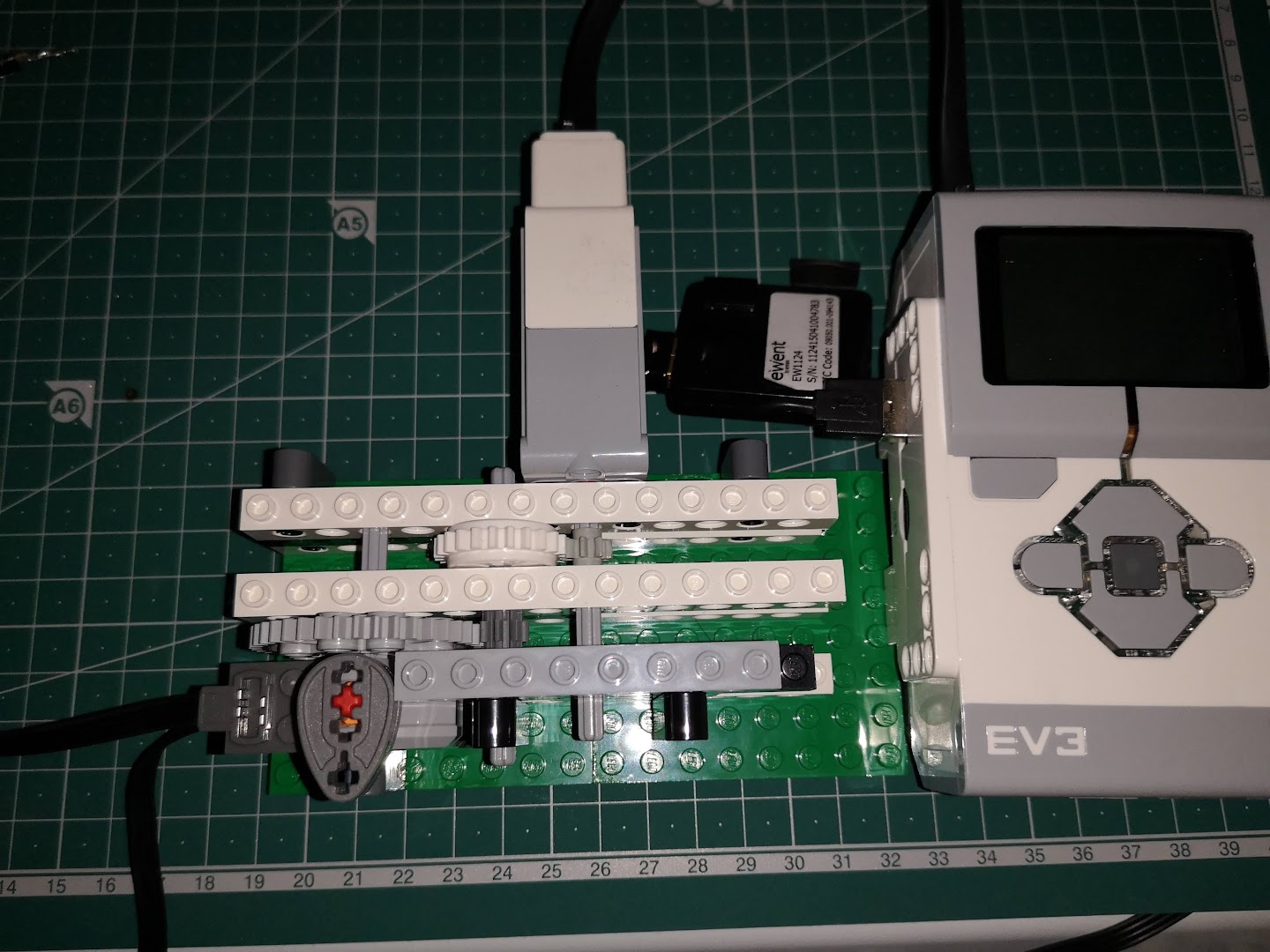
And, of course, I can also connect the XAC to the LEGO MINDSTORMS EV3 running ev3dev.
So what crazy HID shall we create?
Note: the XAC also has Bluetooth. It announces as “Xbox Adaptive Controller” and I can pair it with my Ubuntu but it shows as disconnected (it does connect but when browsing the services it immediately disconnects). Microsoft states that BT only works with Windows 10 so I might need to sweat a bit more before having a wireless controller.