AI2 – selecting BLE devices

This article could also be titled “Read the manual!”

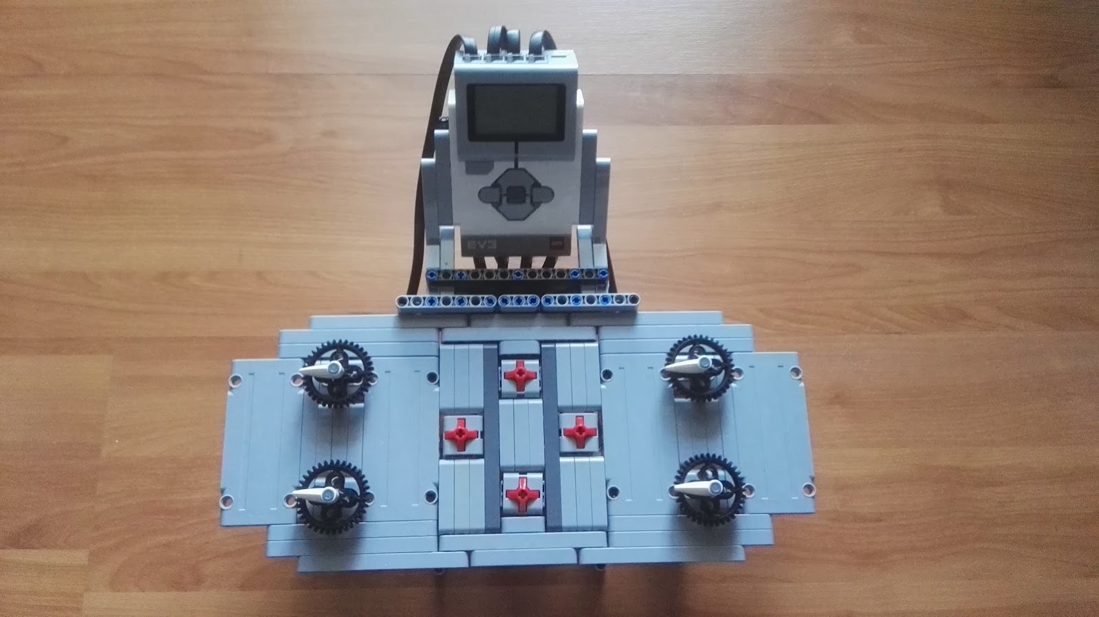
Jetro asked me if it is possible to use the Powered Up smart hub with two train motors in a way that motors work both at same time but in opposite directions. The idea is assembling using a train with one engine wagons at each end like this:

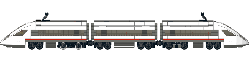
So when the train is moving both motors can be used with just one control.

It is possible with medium motors (my Puppy robot does that when I use the joystick of the App just in a particular axle) and I checked with the only Powered Up train motor I have that it also works (medium motors and train motors seem to have same ID or no ID at all).

So I told Jetro it should be easy to rebuild my App for that specific purpose.

And it really was! Just remove the joystick-related blocks and add two sliders and a few check buttons. So at start only one slider is available and both motors (A and B) run at same speed in opposite directions:

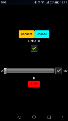
A checkbox allows reversing the direction and the STOP! button quickly stops both motors.

If we want to control the two motors independently another slider appears:

Great, it worked with my Puppy so I asked Jetro for his BT address so I could add to my list of LEGO smart hubs.

But that’s silly!

Yes, I am lazy. But that’s really silly. There must be a way to scan for nearby BLE devices and choose the one we want to use.

So I read the documentation for the AI2 BluetoothLE extension. And they wrote several How Tos including a “Bluetooth Low Energy Basic Connection” that says “Make a basic app that scans for Bluetooth devices and allows you to connect to a selected device”. It also says is for micro:bit and Arduino… but I’m a sceptical old dog.

I didn’t quite copied the example… as I already were using a List Picker button I adapted the example to it.

So these are hte blocks that allow us to use the ‘Choose’ to select which device we want to control:

When the app starts it also starts scanning for nearby BLE devices. The first block above uses “when DeviceFound” to create a list with all devices found. This is list keeps being refreshed while the Scanning process is running.

The list contains the BT Address of each device, it’s friendly name and the RSSI at the time of discovery (a kind of measure of the signal strength that we can use to decide if it is near or far from us).

So when we pick a device from the list (second block above) the text property of the button changes from “Choose” to the friendly name of the device chosen. This name is returned by the “call FoundDeviceName” (not in the original HowTo, that’s why reading documentation is important).

When we press the Connect (or Disconnect) button we now use a slightly different method: “call Connect Index” instead of “call ConnectWithAddress”. I also took the chance to stop the scanning process or restart it (previously the scanning was always running).

So now my App can be used by any one. I feel I’m almost a programmer by now 😀

This is how it works with Puppy:

now I just need to get a second Powered Up train motor to test it with a real LEGO train.

A final note: today at office I found a lots of bluetooth devices nearby. I’m not sure that all are BLE but that’s what the App adds to the list. So I should add a way to filter this list for LEGO-only devices. That means devices whose BT address starts with “”00:16:53” (all my BOOSTs smart hubs) or “90:84:28” (my Powered Up “HUB NO.4” smart hub)… but if LEGO sells lots of these I will probably have to add a few other headers.

EDIT: found a bug when using the APK I built – nothing appears in the listpicker. The BLE extension is lacking proper permissions, you can try the workaround suggested or go to your Android setting and in the App permissions “Your Location” add the App.

MQTT on Windows

I needed to use my Windows 10 Virtual Machine to attend a workshop where labs could only be accessed from Windows operating systems (buh-uh-uh!).

So since I’m back to Windows again, let’s see if If how I can use MQTT on it.

There are two builds of mosquitto tools for Windows: one that it’s based on cygwin and another ‘native’ built with Microsoft Visual Studio

I started with the second: mosquitto-1.4.15a-install-win32.exe

Please note that I’m using a Windows 10 (x64) virtual machine, not quite full updated and it’s July 2018… things might/will change a bit after a while.

So this is x86 (win32) build but it works on x64. It just needs 3 aditional libraries (dll’s) to work:

  • libeay32
  • ssleay32
  • pthreadVC2

The install wizard says that the first and second library can be extracted from the light install of OpenSSL for Windows. But recent versions of OpenSSL no longer use this libraries so I had to download an older one: version 1.0.2o

So I installed this build with the option to include the libraries in the local bin folder where I went to copy “libeay32.dll” and “ssleay32.dll”. Both libraries properties had “file version 1.0.2.15, product version 1.0.2o”.

I copied these 2 files to a new folder “C:\mqtt”

Then I went to POSIC Threads for WIndows project and downloaded the 2.9.1 release and extracted “Pre-built.2\dll\x86\pthreadVC2.dll” also to “C:\mqtt”. File properties had “file version 2.9.0.0, product version 2.9.0.0”.

Then I installed mosquitto 1.4.15a on the same “C:\mqtt” folder, extracting files and configuring the service. This created a Windows Service named “Mosquitto Broker” with a “MQTT v3.1 broker” description, configured as “Automatic” but not started.

From command line, changing to “C:\mqtt” and executing “mosquitto_pub.exe” gives an error stating that another library is missing (MSVCR100.dll). This is from “Microsoft Visual C++ 2010 Redistributable Package” so I installed the x86 version.

Now the same command worked and I could also start the service (“Mosquitto Broker”).

The command line argument are the same as for Linux so

mosquitto_pub.exe -h localhost -m "0" -t sfx -r

works and if I open a second command line window I can see this message arriving:

mosquitto_sub.exe -h localhost -t sfx

Nice. Now I can use LEGO MINDSTORMS, Linux, Raspberry Pi, Android, Arduino and Windows systems on my IoT projects. If someone offers me an Apple OSX device, I’ll be a true polyglIoT ! 😀

Rock Concert IoT

This post is part 5 of 5 of  LEGO Rock Concert

So last days I’ve been assembling the stage surroundings, a truss-based structure to support the left and right video walls and also the self-powered speakers:

LEGO Rock Concert: good progress with the stage and electronics

I gave up hiding the speakers under/inside the stage. I know, speakers aren’t LEGO but I think they look good enough this way.

Also I have been testing the Raspberry Pi Zero W with the PiTFT and a local USB webcam. I use ‘VLC’ to stream the webcam video to the wireless network and can show a stream on the PiTFT with ‘mplayer’. And since mosquitto-clients package is also available for Raspbian I got a way to control everything with just a bash script with MQTT.

So this is the IoT setup now:

LEGO Rock Concert: The IoT

From any mosquitto publisher I can select which stream to show on each video wall and also start a bash script on the EV3 with the sound card and the LEGO Power Function lights so a music plays while the lights blink.

Only problems till now:

  • ‘mplayer’ takes 5 seconds to start playing the stream, doesn’t seem to be a problem with the raspberry nor with the stream, just some kind of warm-up from mplayer, if I can’t fix it will have to find another video player that works with the PiTFT (it’s framebuffer, not X-based)
  • a small USB endoscope camera I was considering using has some problems to show up on first boot of the Rasberry Pi so I will probably use another webcam, bigger but more reliable

While testing the IoT I used my Ubuntu laptop (‘mosquitto-pub’ and ‘mosquitto-sub’) but found a MQTT Dashboard App that works fine both on my Android 5.0 Phone and my Android 4.0 tablet. But I also wanted to use an EV3 as a controller so I tested a few bash scripts with the local keys but found it too limited… so decided to make a better control panel:

LEGO IoT Control Panel

The four medium motors are used as selectors,  I divided a whole rotation in 8 intervals (45º each) to have 8 options on each motor. So it works like this:

– one selector for Video Wall #1

– one selector for Video Wall #2

– one selector for Sound and Lights

– one selector for Special Effects

I can choose what stream I want to show on each video wall and start playing a music. Later I will add more options (photo presentation, youtube video…) and use the 4 EV3 touch sensors to adjust parameters for each option (like the brightness, the frequency or the effect of the lights, the volume of the sound, forward/backward while showing some presentation…).

A video explaining this:

I speak in english but my voice is weak and I had an allergic caugh in the middle so I added sub-titles (also in english).

Video Wall

This post is part 4 of 5 of  LEGO Rock Concert

Xutos’ concert had several projection screens at the background so I want to have at least one small display in the background, above the drum player own stage.

Outdoors concerts sometimes have a videowall or a projection screen at each side of the stage so also want that.

First attempt of a videowall was with a NodeMCU (Arduino-like) and a small  ST7735S based 128×160 display:

It looks great for using as the right/left side displays but there’s not enough power for videos, justs static images (but the NodeMCU has enough internal memory to store a few images so some kind of presentation is possible).

The wiring is SPI so I could use just one NodeMCU to control several displays in parallel (using same Chip Select pin for all) or individually (NodeMCU has a few I/O pins).  I intend to return to this idea later on.

For a “few” more Euros I got a better display, a 2.4″ 320×240 PiTFT for the Raspberry Pi. It’s just a bit larger so it can still used as side displays.

I first tried it with a Raspberry Pi 2, installation is pretty forward:

Unfortunately the RPi is too big and to hide it with LEGO I needed a frame much bigger than the PiTFT. So I opted for a Raspberry Pi Zero W instead:

So the LEGO frame is now smaller and much lighter:

So I just need to repeat the process to have a pair of side displays for my Rock Concert stage.

For the drum player display I think this display is too small so perhaps I’ll try a 3.5″ PiTFT. I could also use a small Android tablet but then I will have problems controlling it – I don’t want to continuously stream video to the displays, I was thinking on using some kind of sensors so the public (real people) could control what to display on it, eventually also control a webcam to show different angles of the concert.

But that’s for another day.

Wireless charger for MINDSTORMS EV3

This post is part 1 of 4 of  Wireless charger

A few months ago I was discussing with Juan about his ideas for a charging station for mobile robots. He was already creating several prototypes but I remember suggesting a wireless circuit, an idea that kept bumping inside my mind until a few weeks ago when I found a very cheap (less than €2,5) Qi receiver at bangood:

Qi receivers for mobile phones supply only 5V through the USB plug but we can use a boost circuit to raise the voltage. This circuit advertises an output current of 1A, if true (we never know, do we?) doubling the voltage to 10 Volt would reduce the output current to 500 mA with an ideal boost circuit. There are no ideal circuits but at least 400 mA is expected, not great but enough to charge a LEGO robot so lets try…

The remain parts are simple:

Any breakout board is fine as long as it exposes the GND and 5V pins, I got one at a local store for less than €2

There are other models, even cheaper, but I also got this one from a local store and it works good: 2 input pins, 2 output pins and an adjustment potentiometer, that’s it!

– a power plug compatible with LEGO EV3 battery

I cannot suggest a proper plug because I’m not 100% sure of the size… I think it is a 1.7 mm jack like this from Amazon:

I simply cut a plug from a cheap wall charger I had around (not the LEGO one! :D)  so I didn’t even had to solder wires

– a couple of wires, preferably red and black

That’s it!

Assembling is very easy so I’m not even goig to draw a circuit:

  1. solder 2 wires to the microUSB breakout board +5V volt (or VBUS) and GND pins
  2. solder the other end of those 2 wires to the input pins of the boost circuit (GND to IN- and +5V/VBUS to IN+)
  3. solder other 2 wires to the output pins of the boost circuit (OUT+ and OUT-)
  4. solder the other end of thos 2 wires to the jack (OUT- to the outter metal part, OUT+ to the inner part)

Here a picture with all soldered:

Then you need a voltmeter to adjust the output voltage. Put the Qi receiver over a Qi emitter and assure it’s coupled (most of them give some kind of visual indication of the coupling state like a blue LED) and trim the potentiometer with a small screwdriver until you got 10.0 Volt (you can use higher or lower values but higher will mean less current available so more time to charge and lower might not be enough for the internal circuits of the EV3 battery to work properly).

In this video you can see the green LED of the EV3 battery blinking – that’s part because the Qi receiver wasn’t properly aligned with the Qi emitter,  part because both Qi components are low-end quality (the emitter is from a friend, it was a gift at an HP event) and finally part because the Qi emitter was being powered up from my laptop – after switching to a 3.1A wall adapter USB charger I got better performance, even a few millimeters of spacing.

Stage Lighting

This post is part 3 of 5 of  LEGO Rock Concert

So the stage size is settled, it will use 3×3 LEGO standard baseplates (32×32 studs each).

Now time to think about the lighting.

For the first version I wanted to be able to control each of the spotlights individually. To minimize wiring I decided to use a 1-wire bus (2 wires for power, 1 wire for data) and I found a 1-wire USB controller that worked very well with linux and (of course) with ev3dev.

I was very happy with the Ev3 1-wire network but not so happy with the way I wired it with my LEGO trusses. I tried to create a pluggable system that would allow me to easily extend the number of spots but never got a decent and discreet solution so I use only fixed size wires, soldered in a daisy-chain. It worked but “locked” my spotlights to the trusses permanently.

So for this new version I decided to use just one or two control channels and use common LEGO Power Function lights (well, at least for this year).

As for the trusses that support the spotlights I also decided to try non-Technic parts – I liked my previous design with only Technic parts but it was already noticeable that the spotlights were too heavy and the 32L axles were bending.

Since LEGO has a truss brick already, lets try it:

So 1 one channel is easy: each Power Functions Light assures 2 spotlights and I just need to daisy chain several of them. We can even make the lights blink with just a electro-mechanic controller like In this video:

Unfortunately it makes to0 much noise so I will have to use something purely electric.

Xutos’ 25th Anniversary concert was indoor (at ‘Pavilhão Atlântico’, currently named ‘Altisse Arena’) and the lights were suspended from the ceilling so there were no vertical trusses in front of the band. If I can’t  keep it realistic I can try a mix: keep the X-shaped stage used in that concert but use a dome truss similar to this model they used in several outdoor concerts in the last couple of years:

So I tried an arch with the LEGO trusses to see it stands hold:

Then I added the Power Functions lights but since the weight was too much I had to redesign it a bit, ending with a much larger arc:

It holds ‘per se’ but is not stable at all, tending to fall to the front or to the back. So a second or even a third arc was needed and also had to raise it a bit because when wife saw it she said the lights were too low and that would prevent people to see the stage. And since wife is always right…

This has been holding tight in our leaving room for the last 7 days (and we have 2 kids!) so I’ll might just reinforce the middle connections of the trusses that have Power Functions cable extensions.

This is already a 2-channel system so I can control half of the spotlights at any time. So it’s a proper time to finally add a MINDSTORMS EV3 to the project… and since I already got six small battery-powered active speakers I can also play a music:


The stage

This post is part 2 of 5 of  LEGO Rock Concert

The main part of the Rock Concert is the stage so it will set the scale of all the diorama.

In the first version, the stage had a few internal gears that allow my kids to move the minifigures of 4 of the 5 elements of the band with a stick at the backstage. I had the idea to animate all 5 but never got a solid way to move the arms of the drum player (“Kalu”) so I left him static and put “Zé Pedro” walking along the stage with his guitar (he is/was a bit wild at stage, once he even broke a leg jumping to a speaker) and the remain three just turning around on their places (“Tim” the bass player and main vocals, “João Cabeleira” the human statue that plays guitar and “Gui” with his saxophone).

A second version had 4 LEGO mini-motors instead of sticks and a LEGO MINDSTORMS EV3 controlling the motors… through a USB 8-relay board! It was one of my first experiments with ev3dev and I had no idea how to control those old motors so I used the relay board I had bought for the Raspberry Pi… it was also the first time I invoked bash scripts from python:

This new version will probably have a similar setup (without relays) but for now I’m just concerned with settling the dimensions.

As I had big bunch of red tiles from a LEGO 10 kg box I decided to make the X-shaped stage:

Yeah, ugly but that’s a start. A few more pieces from Bricklink and things started to get better:

So a few more bricks from Bricklink and lots of funny-blue tiles from the same 10 kg box and the main part of the stage is done:

I’ll increase size a bit more to left/right but the ‘X’ will stay this size.

Height is also good because it will allow me to put small speakers inside and probably a few other things if/when I decide what special effects I will have on stage.

Work in progress: LEGO Rock Concert

This post is part 1 of 5 of  LEGO Rock Concert

Got myself an anti-stress project: rebuild my LEGO Xutos&Pontapés rock concert.

About 30 years ago my cousin took me with him for a rock concert in the town next by: Xutos&Pontapés. I was a kid with almost no interest in music but Xutos had recently released their third LP and finally got some country-wide success, everybody were singing their singles so… why not?

I got hooked! Xutos were a great live band and after all those years they still are.

So my late teenage years as also my first adult years were strongly influenced by their energy. At college I made the first related site (pew! ugly!) and when I got married my tie had their ‘X’ stamped.

A remarkable concert I went to was the one that ended their 25th anniversary tour. The stage had a fabulous ‘X’ shape:

Xutos&Pontapés – XXV year tour

This photo was taken more or less from the same spot where I was.

So this is going to be my crazy project for the next months: a LEGO rock concert that pays tribute to the greatest portuguese rock band ever.

Of course, this isn’t a static LEGO project. Will try to use some of the gadgets and tricks I’ve been using those last 3 years since I joined PLUG.

From the first version I will certainly keep the animated minifigures and the stage lights (but the lights will be pure LEGO now… as much as I like the 1-wire lights concept, soldering and wiring was a mess and this is a purely for-fun project, no need for more stress).

So MINDSTORMS EV3 running ev3dev is expected, probably with one of the new Power Functions 2 devices. And of course at least one Raspberry Pi and a NodeMCU or other Arduino-like board. And webcams, displays, sound speakers, perhaps some special effects… we’ll see.